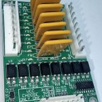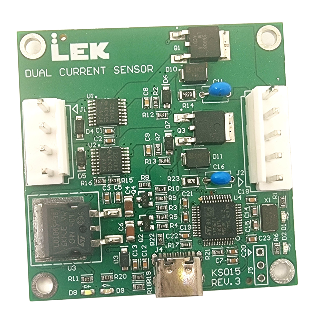
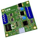
Key Features
- Open development platform — an experimenter’s board
- Arduino / STM32duino — STM32F103C8 can be programmed over USB-C after loading stm32duino, no external programmer
- Dual-channel monitoring — INA260 current, voltage and power on two independent channels
- Load control — two P-channel MOSFETs with transient protection, switched independently
- USB comms experimentation — CDC-VCP, HID, etc
- Full hardware access — I2C bus, INA260 alert lines, load-switch pins and SWD debug header all brought out
- Flexible power — runs from USB-C or either channel input; works stand-alone without USB
- Wide ranges — 5 V to 27 V DC inputs, up to 7 A monitored per channel
Description
The KS015 gives you real power hardware to write firmware against. Each channel pairs a Texas Instruments INA260 current/voltage/power monitor on I2C with a P-channel MOSFET load switch, so a single board covers current sensing, high-side switching, and USB host communications at the same time.
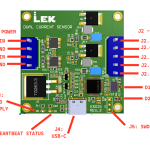
Load up the STM32F103C8 with the stm32duino bootloader, then upload your Arduino IDE sketch over USB-C — nothing else to buy, nothing to configure. When you outgrow that, the SWD header (J5) takes you straight to bare-metal STM32 development with a debugger attached. The same board supports all levels of experience.
Everything is exposed rather than abstracted: the I2C1 bus (PB6/PB7) with the INA260s at 0x40 and 0x41, the alert lines on PB11/PB12, and the load-switch gates on PB0/PB1.
Good for experimenting with: Arduino and STM32duino development on the STM32F103C8 · USB device communications, starting from a virtual COM port · high-side current, voltage and power measurement with the INA260 · P-channel MOSFET load switching and safe-operating-area limits.
📝 Blog post | 📄 Datasheet | 💻 GitHub (firmware) | 💻 GitHub (bootloader)
| MCU | STM32F103C8 (ARM Cortex-M3, 72 MHz, 64 KB Flash, 20 KB SRAM) |
| Current sensor | 2x TI INA260 (I2C, 0x40 / 0x41) |
| Load switches | 2x P-channel MOSFET |
| Max input voltage | 27 V DC per channel |
| Max load current | 7 A per channel |
| MCU operating current | 3.5 mA (typ) |
| Interface | USB-C, SWD |
| Firmware | Arduino-compatible (STM32duino) |
| Weight | 0.1 kg |
KS015 Dual Current Sensor Dev Board
5 in stock
✈ Worldwide shipping
📍 Ships from Singapore