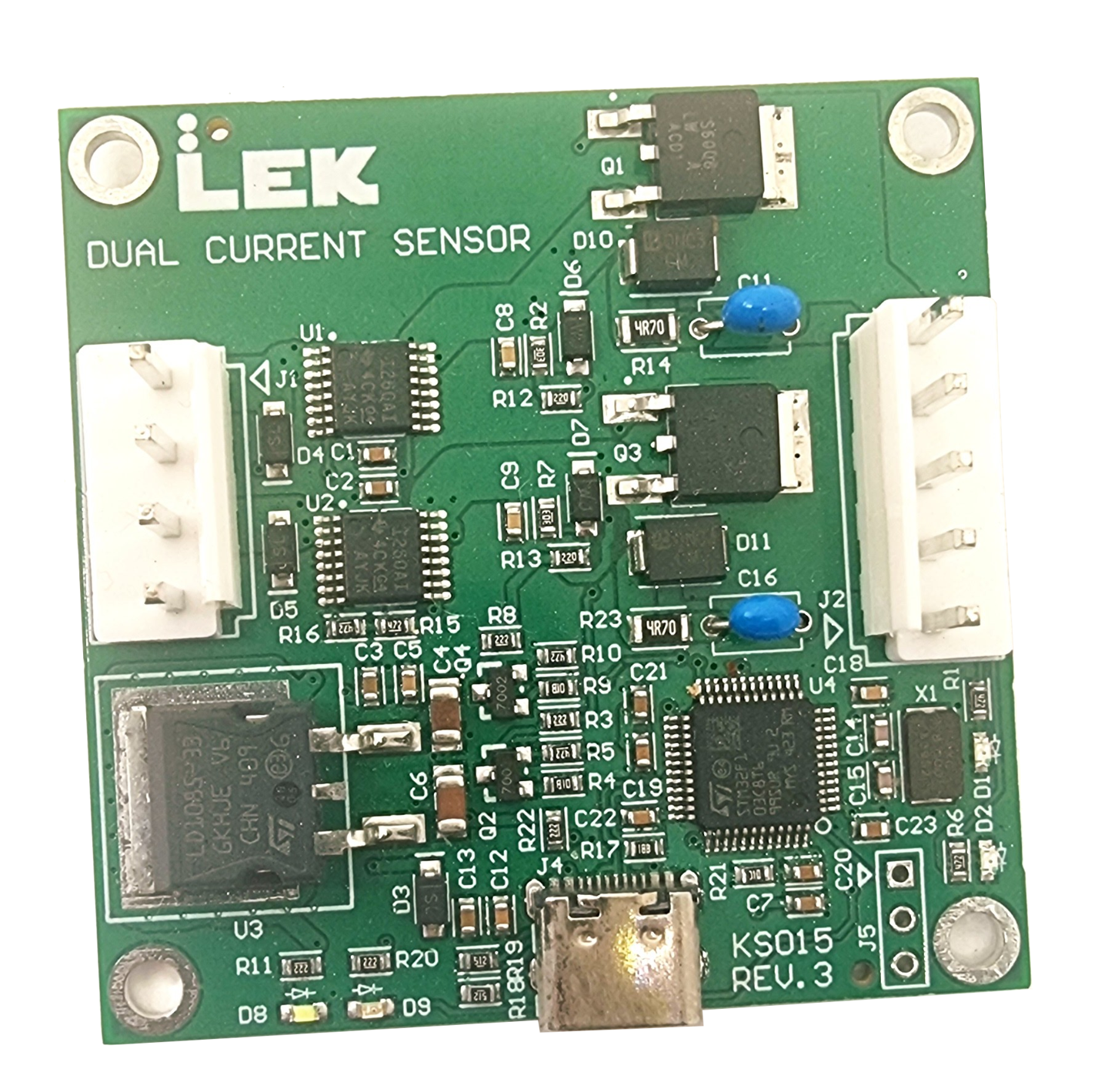
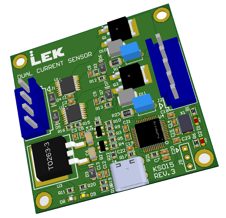
The KS015 is our dual-channel current sensor and load-switching board. It measures current, voltage, and power on two independent channels and can switch each channel’s load on or off under firmware control. It’s designed to be easy to start with — program it from the Arduino IDE over USB — and straightforward to extend all the way to bare-metal STM32 development when you need it.
What it does
Each channel pairs a Texas Instruments INA260 current/voltage/power monitor with a P-channel MOSFET load switch. The INA260 reports live readings over I2C and fires a hardware alert interrupt when a configurable threshold is crossed. The MOSFET switch is driven by the MCU, giving per-channel on/off control with transient protection built in.
The board accepts up to 27 V DC per channel and handles up to 7 A load current per channel. Power can come from USB-C or from either channel’s input rail, whichever is highest; the board automatically selects the best available source.
Architecture
The MCU is an STMicroelectronics STM32F103C8 — ARM Cortex-M3 at 72 MHz, 20 KB SRAM, 64 KB Flash, USB 2.0 Full-Speed. We ship it with a modified STM32duino bootloader (heartbeat LED reassigned to PA3), so uploading new firmware is just the Arduino IDE plus a USB-C cable — no ST-LINK, no proprietary software.
Both INA260s share a single I2C1 bus (PB6/PB7). Channel 1 is at address 0x40, channel 2 at 0x41. Alert interrupts land on PB11 and PB12 respectively. The load switches are driven from PB0 (channel 1) and PB1 (channel 2). Thermal protection is a firmware responsibility — the INA260 provides all the data needed to detect an overload; acting on it (disabling the switch) is up to the application.
Connectors and pinout
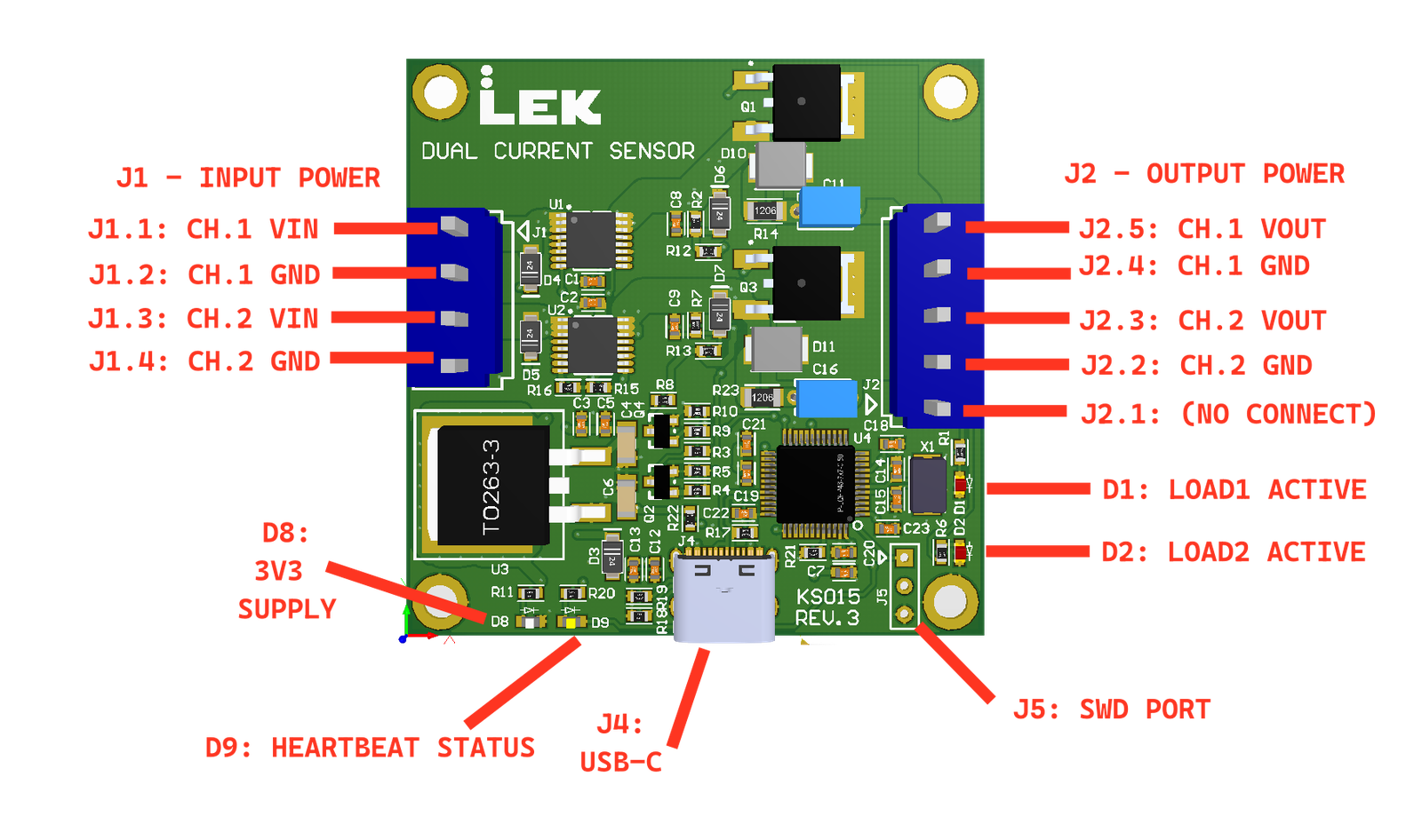
- J1 (4-pin, left edge): Channel 1 VIN + GND, Channel 2 VIN + GND — the two independent power inputs
- J2 (5-pin, right edge): Channel 1 VOUT + GND, Channel 2 VOUT + GND — switched outputs
- J4 (bottom edge): USB-C — power and virtual COM port
- J5: SWD — Serial Wire Debug port for in-circuit debugging and flashing without the bootloader
Four status LEDs give instant visual feedback: a white power LED (MCU power present), a yellow heartbeat LED toggled by firmware (PA3), and two red load LEDs that light when the channel has input voltage and the load switch is enabled.
Getting started with the Arduino firmware
The reference firmware is on GitHub: LekElectronics/STM32-Dual-Current-Sensor (bootloader). It wraps both channels in a KS015 class with a straightforward API:
#include "KS015.h"
KS015 board;

void setup() {
    board.begin();  // initialises INA260s, load switches, heartbeat, Serial at 230400 baud
}

void loop() {
    float mA  = board.getCurrent(CHANNEL1);
    float V   = board.getVoltage(CHANNEL1);
    float mW  = board.getPower(CHANNEL1);

    board.enableOutput(CHANNEL1);   // turn load switch on
    board.disableOutput(CHANNEL1);  // turn load switch off
}
The included KS015_Dual_Current_Test.ino sketch opens a serial menu (230400 baud) for interactive testing: read live channel data, toggle load switches, and run a stress test that cycles a channel on and off in 2-second bursts. It’s a useful first-run confidence check before writing your own application firmware.
Safe operating area
The 7 A load current limit is a tested, single-channel figure in a ventilated location. The P-channel MOSFETs can handle more current electrically, but the actual safe limit depends on ambient temperature, airflow, duty cycle, and whether both channels are loaded simultaneously. The firmware is expected to monitor voltage and current actively and cut the load if either channel approaches its thermal limit — the INA260 gives you everything you need to do this.
SWD escape hatch
If you want to go beyond Arduino — custom bootloaders or low-level peripheral configuration — J5 exposes the full SWD interface. Connect an ST-LINK or compatible debugger and use STM32CubeIDE or OpenOCD to flash and debug directly, bypassing the bootloader entirely.