Background
Almost every device in a typical living room — air conditioners, soundbars, TVs, Blu-ray players, projectors — speaks IR. That’s great until you want to fold them into a home automation setup, at which point you hit a wall: how do you send an IR command from software? The KS019 solves that. It’s an ESP8266-based board that lets you point any IR remote at it, decode exactly what protocol and codes it’s sending, and then fire those codes on demand over WiFi. No cloud, no proprietary hub — just a small PCB you flash yourself and wire into whatever automation stack you’re running.
Hardware
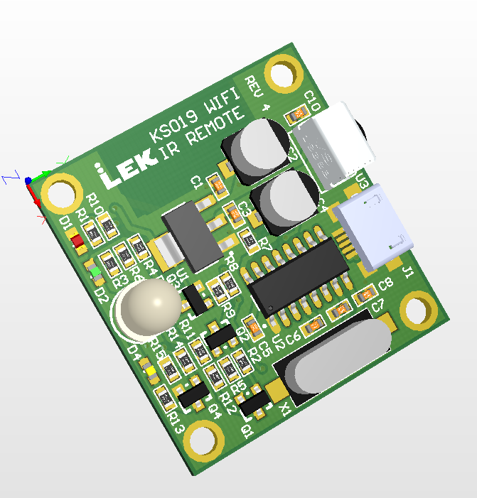
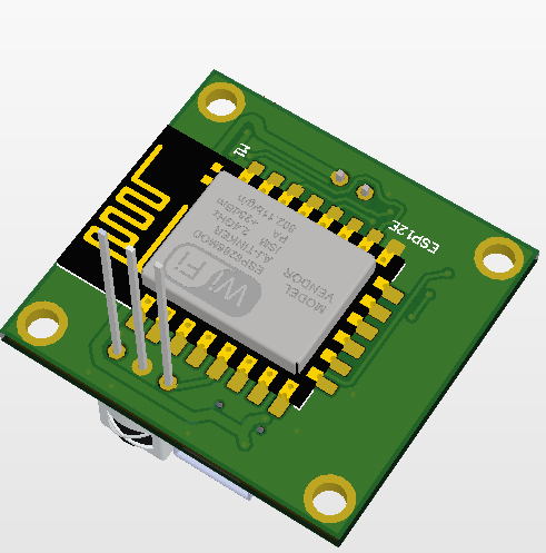
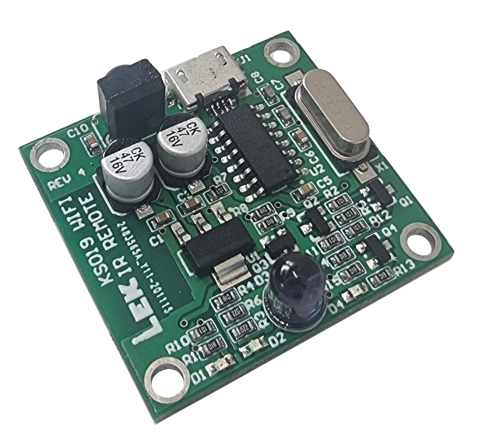
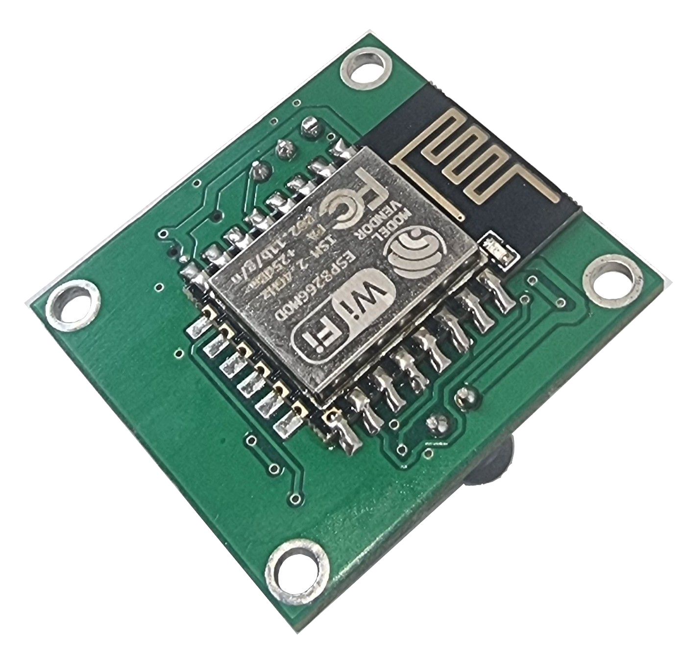
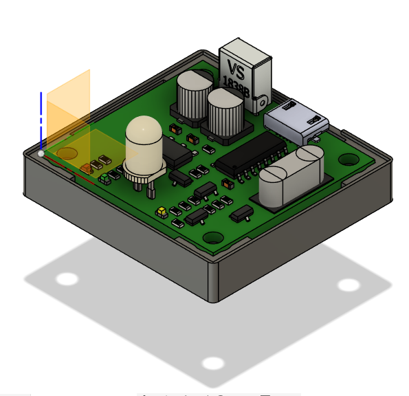
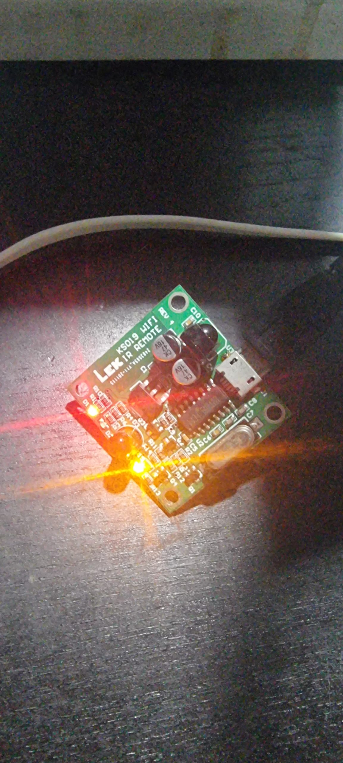
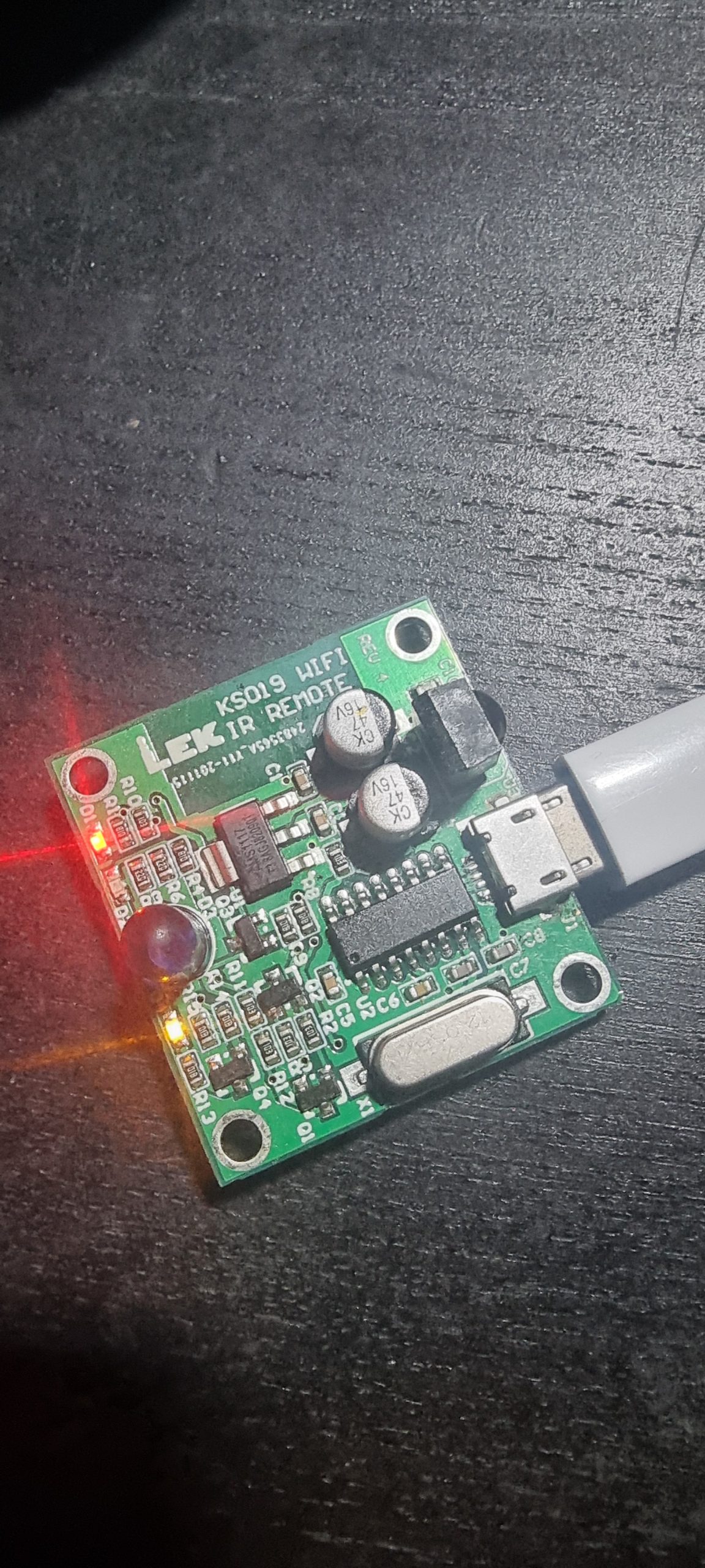
The brains is an ESP8266 — handling WiFi, MQTT, and IR signal generation all in one chip. The IR LED sits on GPIO16 and the IR receiver on GPIO14. Three indicator LEDs tell you what’s happening at a glance: a power LED, a heartbeat status LED on GPIO5 that blinks to confirm the firmware is alive, and a dedicated IR transmit LED that fires each time a code goes out. A micro-USB connector handles both power and programming — plug in, hit upload from the Arduino IDE, done. No FTDI adapter, no boot button gymnastics. An RTS/DTR auto-reset circuit handles bootloader entry automatically. IR transmission has been tested at 10 m between two KS019 units. The board is 33 × 31 mm, prototyped at JLCPCB, and designed in Altium. Print files for a snug enclosure are included.
Enclosure
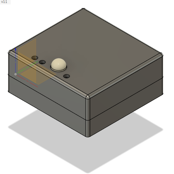
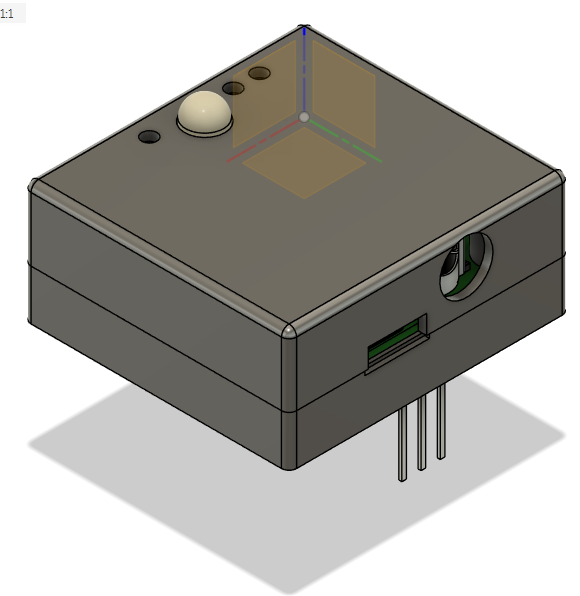
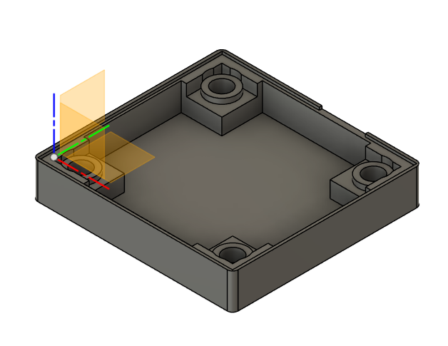
A custom enclosure keeps the PCBA clean and mountable. Validated on a Prusa MK3S+ using eSUN PLA+ filament — no supports required, PCBA drops straight in. Should be printable on any FDM machine.
Arduino IDE setup
If you haven’t used an ESP8266 with the Arduino IDE before, you’ll need to add board support and a couple of libraries. One-time setup:
- Open File → Preferences and add the following URL to the Additional boards manager URLs field:
http://arduino.esp8266.com/stable/package_esp8266com_index.json - Open Tools → Board → Boards Manager, search for esp8266, and install the package from ESP8266 Community.
- Select Tools → Board → ESP8266 Boards → Generic ESP8266 Module.
- Open Sketch → Include Library → Manage Libraries, search for IRremoteESP8266 by David Conran, and install it.
- For the MQTT-based sketches (MideaSend, PanasonicSend): in the same library manager, search for MQTT by Joel Gaehwiler (256dpi) and install it. Note: this is not PubSubClient — the sketches use
MQTTClient.hfrom the arduino-mqtt library.
Firmware workflow
The IRremoteESP8266 library does the heavy lifting — it decodes and encodes a huge range of IR protocols, including the AC-specific ones that carry full unit state (mode, temperature, fan speed, swing) rather than just raw on/off codes. Adding a new device is a two-step process:
- Capture: flash
IRrecvDumpV2to the KS019 and point the original remote at the IR receiver (GPIO14). Each button press is decoded and printed over serial — protocol name, bit count, address, command, and a ready-to-pastesendXxx(…)call. - Replay: drop those values into a transmit sketch. For AC units, the library manages the full state frame so you’re not manually constructing 200+ bit packets.
Deployments
Three transmit sketches have been written so far — each targeting a different device and protocol:
MideaSend
Targets a Midea split AC using the Coolix protocol. Listens over MQTT and responds to ON / OFF — ON sends a fully encoded Coolix frame set to 23°C, cool mode, auto fan. A straightforward starting point if you want to adapt it to your own Coolix-compatible unit.
PanasonicSend
Targets a Panasonic split AC using the kPanasonicRkr model variant. Worth understanding the AC protocol here: unlike a TV where each button sends an independent code, AC remotes transmit the entire unit state in every frame. The library handles this correctly — a single ON command encodes mode, fan speed, temperature, and swing into one complete frame. Auto swing enabled on both vertical and horizontal axes.
SonySend
Targets a Sony soundbar using codes captured from a Sony RMT-AH412U remote. Unlike the AC sketches, this one skips MQTT and is driven directly from the Serial Monitor — type a command name and hit Enter. Handy for quick testing or for setups where serial is more convenient than WiFi. Type help for a full command list.
All codes were captured with IRrecvDumpV2. A useful Sony quirk: decodeSony() stores results.value in the same bit order that sendSony() expects, so you can replay the raw captured value directly without any bit manipulation. The table below lists all captured codes — 15-bit for core amp functions, 20-bit for extended settings.
| Command | Bits | Data | Function |
|---|---|---|---|
power | 15 | 0x540C | Power toggle |
volup | 15 | 0x240C | Volume up |
voldown | 15 | 0x640C | Volume down |
mute | 15 | 0x140C | Mute |
swplus | 15 | 0x1D0C | Subwoofer level up |
swminus | 15 | 0x5D0C | Subwoofer level down |
input | 15 | 0x4B0D | Input select |
menu | 15 | 0x770D | Menu |
up / down | 15 | 0xF0D / 0x4F0D | Navigation |
standard | 20 | 0xB8116 | Standard sound mode |
music | 15 | 0x490D | Music sound mode |
cinema | 15 | 0x610D | Cinema sound mode |
autosound | 20 | 0xF4116 | Auto sound mode |
voice | 20 | 0x9C114 | Voice mode |
night | 15 | 0x20D | Night mode |
play | 20 | 0x5C110 | Play/Pause |
prev / next | 20 | 0xC110 / 0x8C110 | Previous/Next track |
back | 20 | 0xBE110 | Back |
dimmer | 15 | 0x40D | Display dimmer |
enter | 15 | 0x180C | Enter/OK |
Testing
Before shipping, each unit goes through a loopback test that exercises every functional path: USB power, status LED, WiFi, MQTT, IR transmit, and IR receive. You need two KS019 boards — one as the unit under test (UUT), one as a known-good IR witness receiver — placed 10 m apart.
- Load the UUT with
PanasonicSendfirmware. Power via USB and confirm the status LED is flashing — this validates USB power and firmware boot.
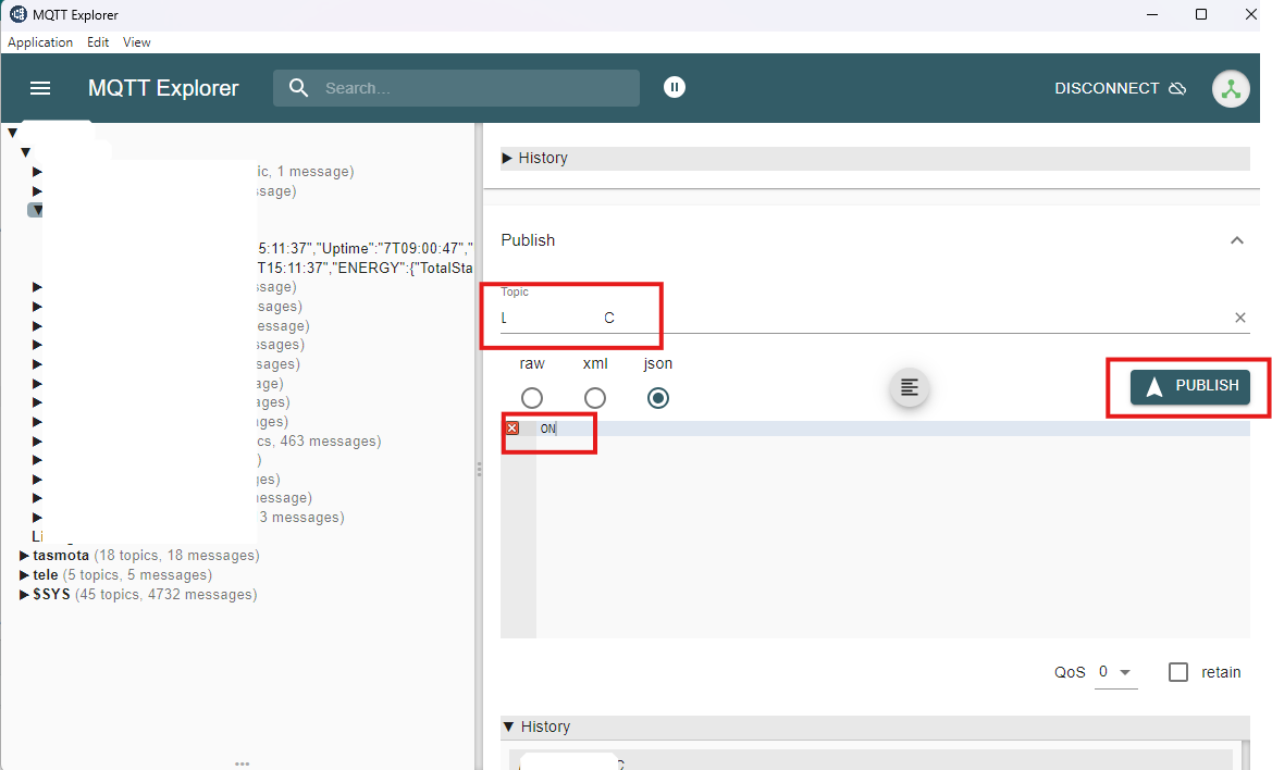
- Use MQTT Explorer to publish
ONto the AC topic. If the UUT has joined the WiFi network and its MQTT subscription is live, it will fire the IR code immediately.
- Load a second KS019 with
IRrecvDumpV2firmware and open its Serial Monitor at 115200 baud. This unit acts as the IR receive witness.
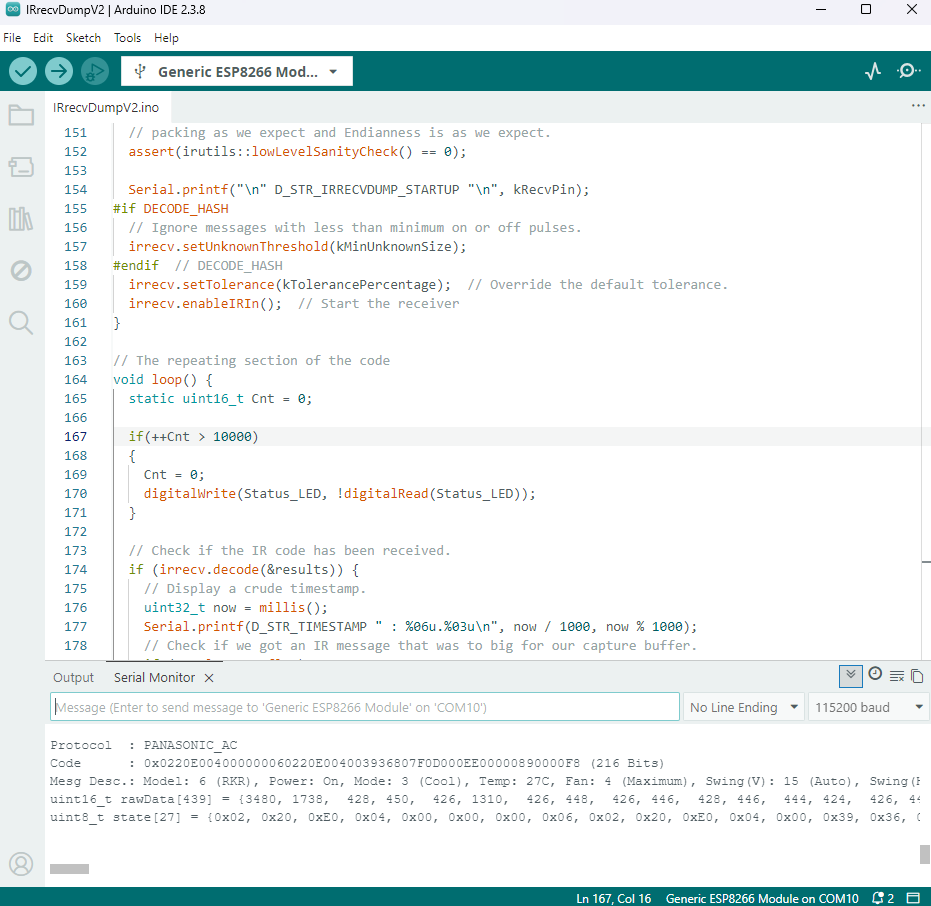
- Confirm IR reception on the witness unit: the Serial Monitor on the second KS019 should decode the incoming Panasonic AC frame — protocol, model, temperature, fan speed, swing. A clean decode here proves the UUT’s WiFi, MQTT stack, and IR transmitter are all working.
- Test the UUT’s IR receiver: reflash the UUT with
IRrecvDumpV2and fire some IR codes at it from any remote. A decode on the Serial Monitor confirms the receiver path is good. At this point every functional block has been exercised. - Ship: leave
IRrecvDumpV2loaded as the as-shipped firmware — it’s the most useful starting point for a new setup. Pack the PCBA into an anti-static bag.
Notes
IRremoteESP8266 covers an impressive range of consumer IR protocols and is actively maintained. For anything exotic it doesn’t recognise, the raw timing capture in IRrecvDumpV2 lets you record and replay arbitrary signals — you lose protocol decoding but you can still brute-force replay any code.
The RTS/DTR auto-reset circuit is one of those things that sounds minor until you’ve spent five minutes holding a wire across GPIO0 while trying to reflash. If you’re designing your own ESP8266 board, put this in from day one.
Sony SIRC is spec’d to repeat each transmission at least twice; three is more reliable. The repeat parameter in sendSony(data, bits, 2) handles this — pass 2 and the library sends three copies total.